Making a Lucas Fuel Pump Transistorized
By Bob Bidger – St. Johns AHC
Reason for Modification:
In the stock fuel pump, a heavy solenoid armature (iron slug) is positioned partially inside a donut-shaped coil of wire. When the key is turned on, an electrical current flows through the contact points to ground.
This current flow creates a strong magnetic field in the coil. This magnetic field draws the armature fully into the coil. This action draws fuel from the tank into the pump cavity.
When the armature reaches full stroke, a rod on the top of the armature pushes the contact points open.
When the contact points are opened, the magnetic field collapses, releasing the pull on the armature. A return spring pushes the armature out of the coil and the fuel out of the pump cavity to the carburetors. When the armature is pushed to it’s starting position, the contact points are closed and the whole cycle begins again.
We are concerned with is what happens ELECTRICALLY when the contact points are opened. As stated above, opening the contact points causes the current flow to stop and the magnetic field to collapse. This collapsing field causes a large “kick-back” current to be generated within the coil. The effect of this current is to create a heavy spark across the opening contact points. This spark causes the contact points to burn and pit. Most point sets have a capacitor across them to absorb this kick-back current. Because there is still a large current load, a capacitor will reduce, but not eliminate point burning.
This modification will use the contact points open and close a set of heavy current “electronic” points. The current load on the fuel pump contact points is reduced from as much as 10 amp’s in the stock fuel pump, to about ¼ of an amp in the modified fuel pump. With this negligible current load, NO point burn will occur.
General:
In order to accomplish the conversion from the stock, point actuated, Lucas fuel pump to a modified, transistor actuated, Lucas fuel pump, you will need the following parts:
| Positive Ground Car | Negative Ground Car |
| PNP Transistor – 10A Archer # 276-2027 |
NPN Transistor – 10A Archer # 276-2020 |
| Diode – 200V – 1A Archer # 276-1102 |
Diode – 200V – 1A Archer # 276-1102 |
| Resistor – 47 Ohm – ½ W Archer # 271-009 |
Resistor – 47 Ohm – ½ W Archer # 271-009 |
The resistor and the diode and the wiring changes are the same for both positive and negative ground conversions. Only the Transistor is different. All of these parts are readily available at Radio Shack, although the part numbers may have changed.
While you are purchasing your parts, buy a small, tweezer style, heat sink. You will need them to prevent heat damage while soldering the transistor and the diode.
If your fuel pump end-cover is not “domed” (one half raised above the other half) this modification will probably not work as there is no space to add the electronics.
The Modification:
Remove the Bakelite cover from the end of the fuel pump. Look at the contact points to see what shape they are in. If the points need replacing, THIS is the best time to do it. NOTE – The points MUST be installed and gapped properly or they will not work correctly.
It is suggested that, at a minimum, you clean and re-contour the point set using a point file or fine emery board. Be sure to clean the points thoroughly.
Being careful not to damage the component, slightly enlarge the hole in the metal tab of the transistor. This is the ground for the transistor so it needs to fit flat to the mounting plate.
Prior to installing the transistor, cut off pin 2 (the middle pin) as short as you can. This pin will not be used.
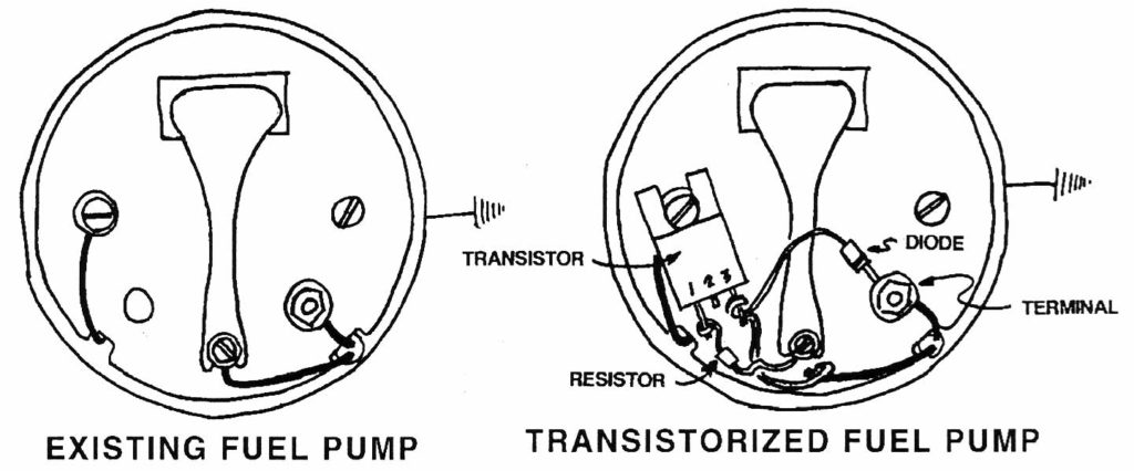
Install the transistor as show in the diagram below:
Add a lock washer under the head of the screw holding the transistor.
Disconnect the lead going to the contact points. Solder this lead to Pin #3 of the transistor. (NOTE: Don’t forget the heat sink on the transistor lead). It may be necessary to lengthen this lead with a piece of connecting wire. See diagram above. Be sure to solder and insulate all wire connections.
Insulate the leads of the resistor and solder the leads between Pin #1 of the transistor (Don’t forget the heat sink) and the screw of the contact points. Solder the lead to the contact points lug first.
Insulate and form the diode leads between the terminal screw and Pin #3 of the transistor.
For NEGATIVE GROUND applications – Insulate and form a “J” in the diode lead that is CLOSEST the STRIPED END of the diode and connect the “J” under the nut on the terminal post. Solder the lead that farthest away from the striped end of the diode to Pin #3 of the transistor.
For POSITIVE GROUND applications – Insulate and form a “J” in the diode lead that is FARTHEST from the STRIPED END of the diode and connect the “J” under the nut on the terminal post. Solder the lead that closest to the striped end of the diode to Pin #3 of the transistor.
Be sure to adjust the contact points such that the pump operates properly.

